EX-HS 203 / 206 / 210 / 220 / 230
|

|
According to LVD 2006/95/EC
test required IEC 60730-1 (4th Edi.): 2010 / IEC 60730-2-6 (2th Edi.): 2007
|
|

|
Certification Criteria
: Protective equipment compulsory safety certification Notice
(Ministry of Employment and Labor Notice 2013-54)
Certification Number : 15-GA2BO-0944X
Certification ratings : Ex d IIC T4 IP67
|
DIMENSION
|

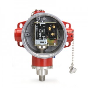
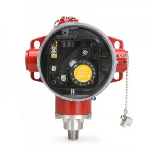
APPLICATION
Explosion-proof box of this product has received safety certification from Korea Gas Safety Corporation to
produce and mount a 3rd party pressure control (pressure switch) at the request of the consumer.
GENERAL SPECIFICATION
|
Ambient temperature
|
Air, Water, Fluorinated refrigerants
|
|
Ambient temperature
|
-15 ∼ 60 ℃
|
|
Medium temperature
|
-10 ~ 120 ℃
|
|
Contact mechanism
|
SPDT
|
|
Protection grade
|
IP 67
6- Dust tight, No ingress of dust
7- Protection against strong jets of water from all
directions.
|
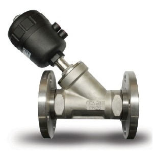
MATERIALS
|
Explosion-proof housing
|
Aluminium diecast
|
|
Internal housing base
|
Iron
|
|
Bellows
|
Bronze
|
|
Connection port
|
Brass
|
|
Diaphragm
|
HNBR
|
|
Pressure connection
|
Stainless steel
|
TECHNICAL SPECIFICATION
|
MODEL
|
Pressure Range
|
Differential Range
|
Factory
Setting On/Off
|
Max.
Bellows Pressure
|
Switch Action
|
|
Bar
|
Psig
|
Bar
|
Psig
|
Bar
|
Psig
|
Bar
|
Psig
|
|
EX-HS 203
|
-0.5 to 3
|
20 to 43
|
0.35 to 2
|
5 to 30
|
0.5/1.5
|
7/21
|
11
|
160
|
Auto Type SPDT opens
High/Low Action
|
|
EX-HS 206
|
-0.5 to 6
|
20 to 87
|
0.6 to 4
|
9 to 58
|
1.5/2.5
|
29/43
|
16.5
|
240
|
|
EX-HS 210
|
1 to 10
|
15 to 145
|
1 to 3
|
15 to 43
|
4/6
|
58/87
|
16.5
|
240
|
|
EX-HS 220
|
5 to 20
|
73 to 290
|
3 to 5
|
43 to 72
|
12/15
|
174/217
|
40
|
580
|
|
EX-HS 230
|
5 to 30
|
73 to 435
|
3 to 10
|
43 to 145
|
15/20
|
217/290
|
40
|
580
|
ELECTRICAL FUNCTION
|
Rated Voltage
Rated Current |
Power Factor
cosϕ
|
AC
|
DC
|
|
125
|
250
|
450
|
25
|
125
|
|
Non-Inductive Current
|
1
|
10
|
5
|
2
|
5
|
0.5
|
|
Inductive Current
|
Running Current
|
0.75
|
8.5
|
4.5
|
1
|
2
|
0.2
|
|
Rocked Roter Current
|
0.45
|
40
|
20
|
10
|
10
|
5
|
PRESSURE ADJUSTING
|
1

[Figure1]
|
[Figure1] Open the cap of pressure range adjusting screw
and the differential pressure adjusting screw.

- If any flammable materials are around, never open.
- Make sure that the power is completely shut off.
|
|
2

[Figure 2]
|
[Figure 2] Loosen the lock as a hexagon wrench and turn the open.
|
3
 
[Figure 3] [Figure 4]
|
[Figure 4]. Insert a screwdriver into the screw hole of the open differential pressure regulation
and pressure ranges, such as turning the screw to adjust the pressure.
|
 - After pressure adjustment, - After pressure adjustment,
be sure to close the lid of the compartment and tighten the cap of screw for the explosion-proof features.
|
|
4
 
|
1. Turn the pressure range adjusting screw to suit the
maximum pressure required.
2. Turn the differential pressure adjusting screw to suit
the needs of differential pressure
3. While operating within a set pressure range, it will be
ON state if it reaches the set differential pressure.
|
■ ATTENTION
All installation/maintenance work must be carried out by skilled staff. Always check that the system is gas-tight after installation.
Failure to follow this manual can result in dangerous situations or damage to the product.
■ INSTALLATION
1. Warning
- Select a product based on the operating pressure,depending on the model specifications table in
this manual before installation.
- All the gas supply must be shut off before installation.
- Make sure that the pipeline is free from impurities and vibration-free before installation.
- Only the "Pressure adjusting screw" and "Differential pressure adjusting screw" can be adjusted.
- Do not bend sharply when pipe connections occur.
- Keep the line length slightly longer to prevent vibration.
- Before opening be aware of risks of dangerous ignition.
- Close the cover tightly before operating.
- Function and holding tests must be carried out after installation.
- When installing to ammonia system, please contact us.
2. Installation Location
- This product can be installed in any position.
■ ADJUSTMENT
Before connecting the pipe, adjust setting value first.
■ Standards and specifications of this product are subject to change without prior notice for improved performance.